 Email Us
KERFED – FRAME ELEVATIONS
- Saved as AutoCad 2010 files.
STEP 1: INSERT and EXPLODE the BLOCK you need into your drawing.
STEP 2: STRETCH as needed.
STEP 3: COPY the Rough Opening lines to the appropriate location and dimension as needed. (NOTE: The Rough Opening stretched with the elevation as it was being modified.)
Frame Elevations are drawn with a solid Polyline. Rough Openings are drawn with a dashed Polyline.
FYI: Rough Openings are measured from the frame rabbet as follows: JAMBS – add 5/8″ per side HEADS – add 13/16″ above
| Elevations A – Frames with 1 3/4″ face | Timely’s casings that create a 1 3/4″ frame face |
 |
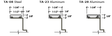 |
| Elevations B – Frames with 2″ face | Timely’s casings that create a 2″ frame face |
 |
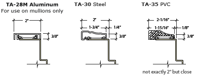 |
| NOTE: The elevation’s “over all” dimensions must be manually modified for wood casings that do not result in either a 1 3/4″ or 2″ face. | |